Friday, May 9, 2014

IxNetwork NGPF: Configure 2 BGP peers and run traffic to prefix list

Scenario:
Configure a eBGP session  between  2  peers that are running BGP over their loopback interface. 
Inject a prefix list  in BGP and run traffic to it from the  neighbour.


Create a BGP peer:
1. Create a topology having one device group with Protocol IPv4 and IPv4 loobback enable

2.Configure interface IP

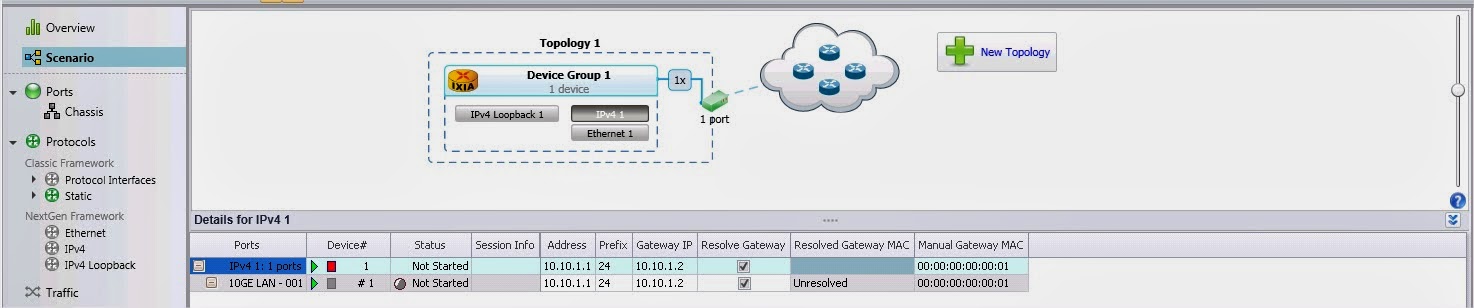
3. Configure  IPv4 loopback address

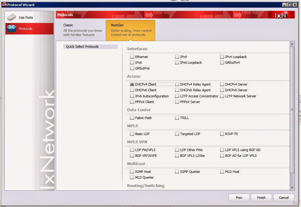
4.  Add protocol over IPv4 loopbak  interface

4.a Select BGP  over Ipv4 loopback address

5. Configure BGP

5.a  Enable filter IPv4 unicast on Learned routes Filter  if you want to see the learned routes in real time


Advertise routes:
6. Add a network group over BGP

6.a Chose Network group type a prefix

6.b Configure the prefix

*** repeat  the first 5 steps for  the second BGP peer
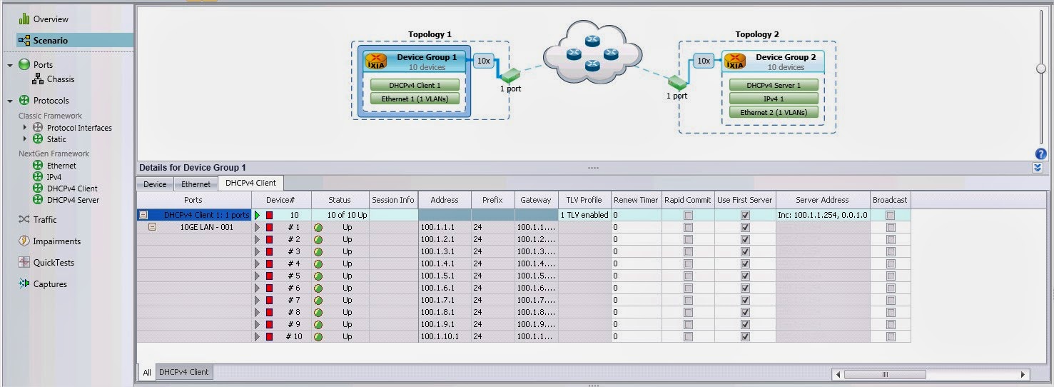
Start scenario
7. Check that routes are advertised using statistics
8. Check the learned routes on the BGP peer
8.a On the peer that is receiving the routes right click on the peer and select Get IPv4 Learned info

8.b Check that all routes are displayed


Send traffic from  Device 2 physical interface 10.10.1.2 to  all prefixes  advertised by its BGP peer

9.a Set the source address as 10.1.1.2

9.b Set the destination address as the prefix list

9.c Enable flow tracking on  IP Destination  Address so you can check that all prefixes are served
9.d Check the flows in Preview 

9.e Start traffic and on Traffic Item tab drill down per destination IP


Thursday, May 8, 2014

IxNetwork NGPF: DHCP example configuration with traffic

Scenario:
Use 2 ports back to back
Configure 1000 DHCP clients each 100  in the same VLAN and  10 DHCP server, one in each vlan. Send L2/3 Traffic from client to his server


We are going to start the configuration by adding just 1 DHCP client in each VLAN

Configure DHCP clients
1.a Go to Scenario and add a port in Topology1


1.b Enable DHCP client on  the port and click finish


1.c Automatically a   Device group containing 10 instances ( default) will appear in topology


2. Go to Protocol Tree->Next Gen Framework subtree and click on Ethernet
  2.a From the master pattern ( blue raw)  enable VLAN


  2.b From master patter set the VLAN as incremental step 1


3. Go to Protocol Tree->Next Gen Framework subtree and click on DHCP client
3.a  From master pattern  configure Server Address as incremental


Configure DHCP server
1.a Go to Scenario and add a new topology


1.b Enable DHCP client on  the port and click finish


1.c Automatically a   Device group containing 10 instances ( default) will appear in topology


2. Go to Protocol Tree->Next Gen Framework subtree and click on Ethernet
  2.a From the master pattern ( blue raw)  enable VLAN and set the VLAN as incremental step 1


3. Go to Protocol Tree->Next Gen Framework subtree and click on IP
   3.a Set the DHCP servers IP addresses

4. Go to Protocol Tree->Next Gen Framework subtree and click on DHCP server
   4.a  From master pattern  set the pool  initial value

   4.b From master pattern  set the pool  size

   4.c  From master pattern  set the pool   gateway


Start DHCP server


Start the DHCP  clients
All the DHCP  clients should obtain an IP address


Modify DHCP client configuration to map 1000 DHCP clients
*** stop the DHCP clients 
1. Modify the number of instances to 1000

2.a Go to Protocol Tree->Next Gen Framework subtree and click on Ethernet
       Change the VLAN ID pattern to Custom from Master raw

2.b Go to Protocol Tree->Next Gen Framework subtree and click on DHCP client
        From master pattern  configure Server Address as Custom


Start devices and check all are up


Create the Traffic
Configure a Traffic Item which sends traffic in each VLAN from the clients to the server
1. Open Add L2/3  traffic wizard
1.a On source side add 10 selection each containing 100 adresses

1.b On destination side add 10 selection  each containing 1 address

*** the selection are paired 1to1  in the order that they were added, for example Selection1 from source side will send traffic only to Selection1 on destination side and so on.

1.c Verify the pattern by  checking the flow groups in preview


2.Start traffic. Check that the load is distributed equally to the destination IP address
*** Enable tracking on IP destination when you create the Traffic Item in order to have this option


Thursday, October 10, 2013

IxNetwork IGMP configuration

*****Configuration steps

1.       Select the ports
Add 2 ports in  the configuration and rename them as IGMP Host and Querier

2.        Enable IGMP protocol on the ports
Click on Protocols  on Protocol tree and then switching to Multicast tab

3.       Configure the IP addresses on the ports
IGMP Querier  IP=1.1.1.1
IGMP Host IP=1.1.1.100
You need to  Add Interfaces and Add IPv4 addresses on the ports
Enable the interfaces, the port link should be green without exclamation mark


4.       IGMP Querier configuration
Go to IGMP  on Protocol tree and switch to Ports tab. Set number of queriers to 1 Number of host to  0

On the Querier tab add the Connected Interface to the   Querier and enable it

Set the querier to use IGMPv3


        5.  Configure IGMP host:
Go to IGMP  on Protocol tree and switch to Ports tab. Set number of queriers to 0 Number of host to  1

On the Hosts tab add the Connected Interface and enable it

 Set host type to IGMPV3


On the Host tab set No of Group Ranges to 1


Switch to Group Ranges tab and set the multicast group for which the IGMP host is member


6.       Start IGMP


*****Tools for troubleshooting
1.       Capture packets
 Go to Captures button and  enable control capture on ports. Click  on Start Capture from Main ribbon


2.       Use  Port Trace  Window:
On  Protocol Tree right-click on a port and chose Open Trace Window. Select the level of debugging.  


      In the Trace Window you see packets received and sent by the port